Why BIM Problems Show Up in the Field Instead of the Model
BIM problems rarely appear in the field because teams ignored coordination. They appear because the model was treated as a design artifact instead of a construction control system. In data center construction, that gap is costly. Power distribution, UPS systems, generators, bus ducts, cable trays, cooling infrastructure, and redundancy paths all compete inside dense mission-critical facilities. A model can pass clash detection and still fail when field crews need installation access, phased sequencing, equipment clearances, or validated A/B pathway separation. The real goal is not a clean model. It is a field-ready coordinated model that protects uptime, schedule, cost, and long-term operational reliability.
Why BIM Problems Show Up in the Field Instead of the Model
BIM issues show up late when coordination stops at visual fit. A duct may clear a cable tray in Navisworks, but the hanger zone, bend radius, access panel, or commissioning requirement may still fail in the field. That is where model accuracy becomes more than geometry.
In data center BIM, the model must reflect field reality. Critical infrastructure does not forgive assumptions. A small routing decision can affect UPS routing, cooling paths, redundancy validation, maintenance access, and commissioning.
The Difference Between Model Coordination and Field Reality
A coordinated model is only useful if it reflects real-world conditions. Field changes, vendor equipment substitutions, slab deviations, and late design updates can quickly make a once-accurate model unreliable.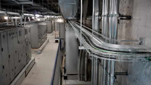
This is why as-built updates and field verification matter. Without them, teams build from a version of reality that no longer exists. The result is field conflicts, RFIs, rework, and schedule delays.
Why Clash Detection Alone Is Not Enough
Clash detection catches geometric collisions. It does not always catch construction conflicts. A model may show no hard clash between conduit runs and chilled water systems, but still leave no room for installation, service access, or future replacement.
Tools like Revit, Navisworks, IFC files, and federated model workflows are powerful, but they need constructability review. Clash-free does not always mean field-ready.
Core BIM Coordination Concepts Behind Field Issues
Strong BIM coordination depends on process, ownership, and field validation. Weak coordination workflows usually create weak field execution.
BIM Coordination Workflows
A proper coordination process moves from discipline models to a federated model, then into issue logs, trade resolution, shop drawings, and field-ready information. The problem starts when coordination meetings only clear clashes instead of confirming how work will actually be installed.
MEP coordination should include sequencing, access, supports, prefabrication logic, and commissioning needs. Otherwise, unresolved design conflicts become field conflicts.
Model Accuracy and Level of Detail
LOD 300 may be enough for design coordination, but data center construction often needs LOD 350 or LOD 400 for fabrication models, equipment clearances, bus duct routing, and conduit layout.
If the model lacks installation-level detail, the field team becomes the place where missing information gets discovered. That usually means delays, change orders, or rework.
Static BIM vs Living BIM
Static BIM freezes too early. Living BIM keeps changing as field conditions, vendor models, linked models, and actual installed conditions evolve.
For mission-critical facilities, living BIM is not a luxury. It is the only way to keep power infrastructure, cooling systems, and phased deployment aligned with reality.
Common Data Environment and BIM Execution Plan
A common data environment and BIM Execution Plan define who updates the model, which version is current, how IFC files are exchanged, and how issue logs are closed.
Without a strong CDE and BEP, teams coordinate against outdated information. That is how model errors survive until installation.
Why Data Center BIM Is More Complex Than Standard Building Coordination
Data centers compress enormous infrastructure systems into limited space. They also require uptime, reliability, redundancy, and thermal performance that ordinary buildings do not demand.
High MEP Density Creates Hidden Coordination Risk
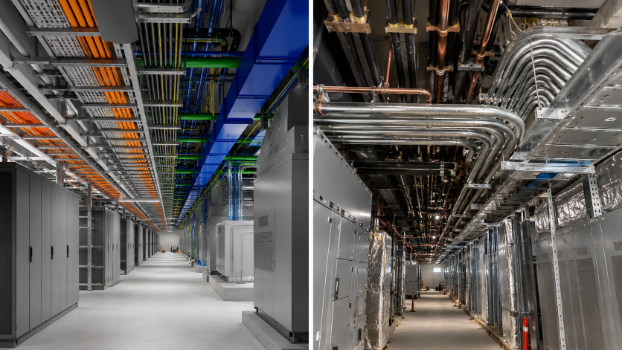
MEP density is one of the biggest reasons problems escape the model. Cable trays, conduit, duct banks, switchgear lineups, cooling systems, containment systems, and structural supports often occupy the same congested zones.
A minor routing issue can block access to critical electrical systems or compromise cooling infrastructure.
Uptime Requirements Change the Meaning of Coordination
In data center construction, coordination is not just about avoiding clashes. It is about protecting uptime targets and fault tolerance.
Redundancy logic, N+1 redundancy, 2N redundancy, and A/B pathway separation must be modeled and validated. If redundant power paths share the same risk zone, the model may look clean but fail the reliability intent.
Phased Deployment Adds More Field Complexity
Hyperscale data center projects are often delivered in phases. Temporary routing, active infrastructure, and future expansion zones make construction sequencing more complex.
If phased deployment is not modeled clearly, field crews may install work that blocks later systems, commissioning paths, or maintenance access.
Electrical Infrastructure: Where BIM Problems Become Expensive
Electrical coordination is where small BIM misses become expensive field problems. Power distribution systems are dense, heavy, sequenced, and reliability-sensitive.
Power Distribution and Electrical Routing
Power distribution must be coordinated from utility entry through switchgear, UPS systems, generators, panels, bus ducts, and branch circuits. Every route has physical, thermal, and operational consequences.
Electrical distribution cannot be treated as simple linework. The model must account for clearances, supports, access, separation, and installation order.
UPS Routing and Backup Power Systems
UPS routing and backup generators need more than space in the model. They need service access, safe working clearances, cable routing, and commissioning paths.
If generator distribution or UPS systems are coordinated too late, field teams may face rerouting, downtime risk, or expensive redesign.
Bus Ducts, Cable Trays, Conduits, and Duct Banks
Bus ducts, cable trays, conduit runs, and duct banks are common sources of field conflict. They may not clash visually, but installation may fail because of bend radius, pulling distance, hanger spacing, or access conflicts.
This is where electrical coordination must move beyond basic clash detection into construction logic.
Redundant Power Paths and A/B Separation
Redundant power paths must remain physically and logically separated. A/B pathway separation is not a drafting preference. It is part of fault domain validation.
If BIM coordination misses redundancy validation, the field may install systems that technically fit but weaken reliability.
Cooling Systems and Thermal Coordination
Cooling interaction is another area where geometry alone is misleading. Thermal performance depends on airflow, cooling load, heat removal, and equipment layout.
Cooling Paths and Airflow Planning
Cooling paths must align with rack density, containment systems, hot aisle and cold aisle layouts, and cable routing. A cable tray that blocks airflow can create hot spots even without a hard clash.
CRAC, CRAH, Chilled Water, and Containment Systems
CRAC units, CRAH units, chilled water systems, and containment systems need coordinated access and clear routing. Their interaction with electrical systems must be reviewed early, not during commissioning.
Thermal Performance Gaps and Hot Spots
Thermal performance gaps often appear after installation because the model did not account for real airflow restrictions. Hot spots are rarely caused by one item. They usually come from poor coordination between power, cooling, racks, and containment.
Field Execution: Where Coordination Quality Is Proven
The field proves whether BIM coordination was real. If crews still need to solve major conflicts onsite, the model was not field-ready.
Installation Planning and Constructability
Constructability review checks whether systems can be installed in the correct order, with enough access and realistic labor movement. This is where avoided field issues are created.
Field-Ready Information for Crews
Field-ready information includes coordinated layouts, shop drawings, fabrication models, and clear installation packages. Crews should not have to interpret design intent under schedule pressure.
How Poor Coordination Creates RFIs, Change Orders, and Rework
The chain is predictable: missing model detail creates field conflict, which creates RFIs, change orders, rework, and schedule delays. Better coordination improves cost savings and project ROI.
Reality Capture, Scan-to-BIM, and Field Verification
Modern BIM must be verified against reality, not trusted blindly.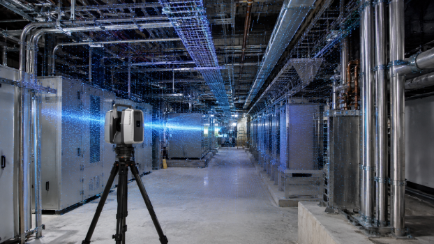
Laser Scanning and Point Cloud Data
Laser scanning and point cloud data capture actual installed conditions before they become hidden problems. This improves model accuracy and reduces late surprises.
Scan-to-BIM for As-Built Accuracy
Scan-to-BIM turns field conditions into usable as-built models. That supports future operations, digital twin development, and maintenance planning.
Field Verification as a Continuous Process
Field verification should happen throughout construction. A living BIM workflow keeps issue logs, field changes, and as-built updates connected.
Prefabrication, Fabrication Models, and Field Productivity
Prefabrication works only when the model is accurate enough to trust.
Why Prefabrication Needs Better BIM Detail
Fabrication models need exact dimensions, connection points, vendor models, and installation tolerances. LOD 400 detail reduces guesswork.
Reducing Waste and Improving Project Efficiency
Accurate BIM coordination reduces material waste, field rework, and labor downtime. It also supports operational efficiency and energy efficiency through better system layout.
Commissioning, Operations, and Long-Term Reliability
For data centers, BIM value continues after construction.
Commissioning Risks from Poor BIM Coordination
Commissioning exposes weak coordination fast. UPS systems, generators, power distribution, cooling load, and full-load testing must work together.

Digital Twin and Operations Handoff
A reliable digital twin depends on accurate as-built models. If the model is wrong at handoff, operations inherits the problem.
Energy Efficiency and Sustainability Outcomes
Sustainability depends on fewer errors, less material waste, efficient cooling systems, and smarter power distribution. Better BIM supports all of them.
Future Trends in BIM Coordination for Data Centers
The industry is moving from clash detection to risk-aware coordination.
From Clash Detection to Predictive Coordination
Future coordination will identify sequencing, access, redundancy, and commissioning risks earlier.
Better Model Segmentation for Dense Infrastructure
Model segmentation by area, phase, system, or fault domain will help teams manage dense infrastructure more clearly.
Connected BIM, CDE, and Field Feedback Loops
The strongest workflows will connect CDE, field verification, issue logs, and as-built updates into one feedback loop.
Conclusion: The Field Should Confirm the Model, Not Correct It
BIM problems show up in the field when models are inaccurate, outdated, under-detailed, or disconnected from construction reality. In data center construction, that risk touches power infrastructure, cooling systems, redundancy, uptime, commissioning, and long-term reliability. The answer is not more modeling for its own sake. It is better BIM coordination, stronger field validation, and a living model that helps crews build correctly the first time.