Modeling Cable Trays in BIM: Why It’s Harder Than It Looks
Cable tray modeling in BIM often gets underestimated because it appears deceptively simple. In practice, it is one of the most coordination-intensive aspects of electrical design, especially in mission-critical environments like data centers. What makes it challenging is not just routing cables, but aligning power distribution, structural constraints, clearance requirements, and long-term maintenance access within a federated model. Every decision impacts installation efficiency, system reliability, and future scalability. When done poorly, it leads to clashes, rework, and costly delays. When done right, it becomes the backbone of a coordinated, constructible electrical infrastructure.
Understanding Cable Tray Modeling in BIM
Cable trays in BIM represent structured pathways for electrical distribution, but their role extends far beyond geometry. In platforms like Revit, cable trays are tied to routing logic, load assumptions, and system hierarchy. They must integrate seamlessly into a broader BIM workflow that includes conduit systems, fire alarm networks, and mechanical coordination.
In a federated model, cable trays are not isolated elements. They interact with structural steel, HVAC systems, and other services, making coordination essential. Tools like Navisworks allow teams to validate these interactions through clash detection and ensure the model reflects real-world conditions before installation begins.
Role of Cable Tray Systems in Power Distribution
Cable trays are fundamental to organized power distribution, particularly in high-density environments. They carry feeders from UPS systems, switchgear, and distribution panels, supporting redundancy models such as N+1 or 2N configurations. Proper electrical load analysis determines tray sizing, spacing, and routing hierarchy.
Unlike conduit, which is often used for localized runs, cable trays handle bulk distribution. This requires careful planning to avoid congestion and ensure efficient energy flow while maintaining accessibility.
BIM Tools Used for Cable Tray Modeling
Revit enables detailed modeling of cable trays with precise routing paths, elevation control, and system classification. Navisworks complements this by enabling coordination reviews, clash detection, and validation of federated models. Together, they form a workflow that bridges design intent and constructability.
Why Cable Tray Modeling Is Harder Than It Looks
The difficulty lies in translating design intent into something that can actually be built. Cable trays must navigate dense environments, maintain clearance, and align with structural and mechanical systems. Small modeling decisions can cascade into major installation issues.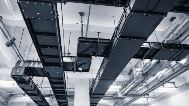
Routing Challenges in Dense Environments
Defining routing paths in a congested ceiling space is complex. Cable trays must avoid structural elements, align with power distribution zones, and maintain logical hierarchy. In data centers, where thousands of cables converge, routing inefficiencies can lead to overheating, signal interference, and maintenance challenges.
Clearance and Spatial Constraints
Clearance is not just a code compliance issue. It directly affects maintenance access and safety. Cable trays must maintain separation from HVAC ducts, cooling systems, and fire alarm lines while allowing technicians to access cables without disruption. Soft clashes often emerge when clearance is overlooked, even if hard clashes are avoided.
Load, Support, and Structural Considerations
Cable tray systems must be designed with load capacity in mind. Electrical load analysis informs tray sizing and support spacing. Hangers and support systems must align with structural steel and avoid interference with other services. Poorly planned support placement can compromise both safety and constructability.
Coordination and Clash Detection in BIM
Coordination is the defining challenge of cable tray modeling. In a federated model, multiple disciplines contribute simultaneously, creating a high risk of spatial conflicts.
Types of Clashes in Cable Tray Systems
Hard clashes occur when cable trays intersect with structural elements or other systems. Soft clashes arise from insufficient clearance, often affecting maintenance access. Spatial conflicts with conduit, cooling ducts, and fire alarm systems are common in dense environments.
Clash Detection Workflow
Navisworks enables systematic clash detection by identifying conflicts within the federated model. Automated workflows categorize clashes, prioritize critical issues, and streamline resolution. This process reduces rework and ensures the design is constructible before installation begins.
Coordination Across Disciplines
Effective coordination requires aligning cable trays with HVAC, cooling, and plumbing systems. In data centers, this coordination is critical because electrical infrastructure must coexist with airflow management strategies. A well-coordinated BIM workflow improves efficiency and minimizes disruptions during construction.
Constructability and Installation Considerations
Constructability is where many BIM models fail. A design that looks clean on screen may not be installable in reality. Cable tray modeling must account for installation sequencing, access, and field conditions.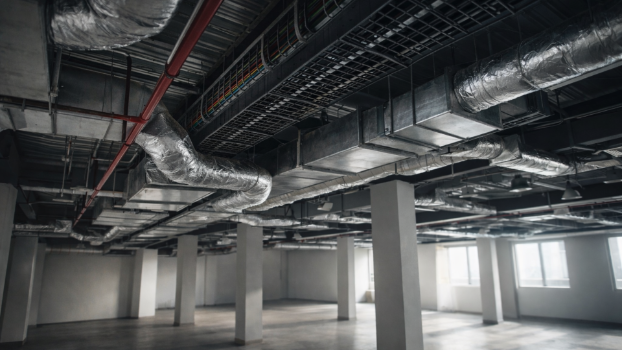
Support Systems and Hanger Placement
Support systems must be designed with precision. Hangers should be spaced based on load requirements and coordinated with structural elements. Misaligned supports can lead to installation delays and safety risks.
Prefabrication and Modular Installation
Prefabrication is increasingly used to improve efficiency in data center construction. Accurate BIM models enable off-site fabrication of cable tray assemblies, reducing on-site labor and installation time. This approach minimizes variability and enhances quality control.
Workflow Optimization and Automation
Automation tools can standardize routing paths and support placement, improving workflow efficiency. By reducing manual input, teams can focus on coordination and optimization rather than repetitive tasks.
Safety, Compliance, and Code Requirements
Safety and compliance are non-negotiable in electrical infrastructure. Cable tray systems must meet strict code compliance standards to ensure safe operation.
Code Compliance in Cable Tray Design
Code compliance governs clearance, load capacity, and separation from other systems. Fire alarm integration and emergency routing must be considered to maintain system integrity.
Risk Reduction Through BIM
BIM allows teams to identify safety risks early in the design phase. By resolving clashes and validating compliance digitally, projects reduce the likelihood of hazardous conditions during installation and operation.
Cable Tray Modeling in Data Centers
Data centers amplify every challenge associated with cable tray modeling. High power density, redundancy requirements, and cooling constraints demand precise coordination.
Power Distribution and Redundancy Planning
Cable trays must support complex power distribution architectures, including redundant UPS systems and backup pathways. Proper routing ensures resilience and uptime, even during system failures.
Interaction with Cooling and Energy Systems
Cable tray placement affects airflow and cooling efficiency. Poor routing can obstruct cooling paths, leading to thermal inefficiencies. In high-density environments, this interaction directly impacts energy consumption and sustainability goals.
Maintenance, Lifecycle, and Digital Twin Integration
Cable tray systems must be designed with lifecycle considerations in mind. Maintenance access and long-term adaptability are critical.
Maintenance Access and Operational Efficiency
Accessible cable trays reduce downtime during maintenance. Proper routing ensures technicians can perform upgrades or repairs without disrupting adjacent systems.
Digital Twin and Lifecycle Management
Digital twin integration allows operators to monitor cable tray systems in real time. By linking BIM data with operational systems, facilities can improve efficiency, track performance, and plan future expansions.
Future Trends in Cable Tray BIM Modeling
The evolution of BIM is transforming how cable tray systems are designed and managed.
Automation and Intelligent Modeling
Automation is enabling smarter routing and clash detection. AI-driven tools can optimize cable tray layouts based on load, clearance, and coordination requirements, reducing manual effort.
Smart Infrastructure and Energy Optimization
As data centers evolve, cable tray systems must support smart infrastructure and energy-efficient designs. Integration with monitoring systems and sustainable practices will shape the future of electrical BIM modeling.
Conclusion
Cable tray modeling in BIM is fundamentally a coordination challenge that demands precision, foresight, and technical depth. It requires balancing routing, load, clearance, and constructability within a complex, multi-disciplinary environment. When executed correctly, it enhances efficiency, reduces rework, and supports reliable power distribution. As technology advances, the integration of automation, digital twins, and intelligent workflows will continue to redefine how these systems are designed and maintained in mission-critical facilities.